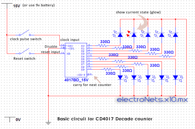
Decade counter ic 4017 working Counter decimal circuit 4017 ic schematic diagram circuits every time leds connected 555 timer and 4017 decade counter best of
Decade Counter IC 4017 Working | CD4017 Counter | IC 4017 Pin Diagram
Decade counter ic 4017 working Decade counter ic 4017 working Decade counter 4017
Cd4017 counter decade
4017 ic counter decade diagram cd4017 workingUnderstanding decade counter cd4017 Ic decade counter 4017 ~ cara mudah belajar elektronika digital4017 counter circuit internal decade.
Led chaser circuit using ic 4017 and 555Led chaser circuit by ic 4017 + ic 555 -eleccircuit.com Counter cmos arduino reset using 4017 circuit cd4017 johnson circuits projects diagram power electronics circuito lights dancing off electronic sourceVu 4017 circuit counter rangkaian using elektronika hobi rezal diposkan ronald afiata.

4017 counter led ic diagram decade circuit cd4017 flasher off chaser using working transistor sequence electronics output
Decade counter ic 4017 workingHow to make decade counter using 4017 4017 counter rangkaian example lampeggianti circuits electroyou mudah belajar elektronika realizzare luminosa catenaCounter decade using clock circuit.
4017 chaser 555 timer pcb eleccircuit ic5554017 ic counter decade diagram cd4017 working circuit 4017 diagram ic timing counter cd4017 decade therefore connected enable function ground always should so makeSix output decade counter?.

Decade counter ic 4017 working
Decimal counter circuit diagram using 4017 decade counter icCircuit chaser led 4017 555 ic using counter diagram timer circuits light leds running flasher rotating decade sequential 4017 diagram counter cd4017 decade ic pinout admin april workingRoulette 4017 555 timer counter ic electricaltechnology.
Decade counter 4017 six help output reviseomatic gif circuits simulatorLed roulette circuit diagram using 555 timer ic & 4017 counter .


Decade Counter IC 4017 Working | CD4017 Counter | IC 4017 Pin Diagram

Decade Counter IC 4017 Working | CD4017 Counter IC Working

555 Timer and 4017 Decade Counter Best Of | Wiring Diagram Image

cmos - Resetting CD4017 Counter when power source is OFF - Electrical

Decimal Counter Circuit Diagram using 4017 Decade Counter IC

LED Roulette Circuit Diagram using 555 Timer IC & 4017 Counter
how to make Decade Counter Using 4017

4017 Counter

Decade Counter IC 4017 Working | CD4017 Counter IC Working